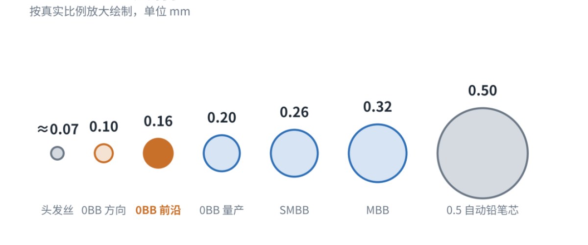
A human hair is about 0.07 mm across. The 0BB ribbon used in modules today goes down to 0.16 mm — barely two hairs side by side — and a module over two metres long contains more than a thousand of these copper wires carrying current from cell to cell.
Ribbon has been getting finer for a decade. The question is whether it can keep going: how much room is left after 0.16 mm? This article pins down what is actually in production, then uses a few simple physical relationships to estimate where round-wire ribbon stops being worthwhile on a module.
What 0BB ribbon is
A conventional cell collects current on dense fine fingers and aggregates it on busbars perpendicular to them; ribbon is soldered onto the busbars. 0BB — zero busbar — removes the busbars at the cell and lets the ribbon contact the fine fingers directly, so the ribbon does the collecting and the stringing at once.
Removing the busbars saves silver: brokerages estimate 10–20% less paste for TOPCon and around 30% for HJT. The higher the silver price, the better the arithmetic, which is why 0BB spread from HJT into TOPCon and BC.
The wire itself is simple — annealed soft copper with a solder coating — but it has to be finer, softer and more uniformly coated than before, and lamination-alloying routes need lower-melting bismuth or indium solders.
How fine is production, really?
| Question | Answer |
|---|---|
| What counts as 0BB ribbon? | Coated round wire of diameter ≤0.22 mm (Tongxiang 2024 interim report; Zhongyuan Securities) |
| What is in volume production? | 0.18–0.20 mm confirmed by multiple sources; 0.16 mm is the finest publicly documented application (Jolywood patent range 0.16–0.22 mm) |
| What is technically possible? | 0.14 mm already demonstrated in laboratories; one major ribbon maker has said 0.10 mm is the direction |
Why finer is attractive
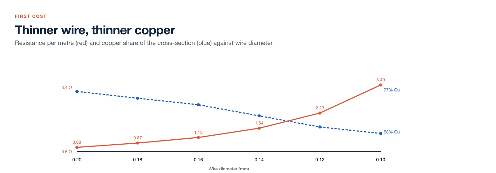
Four benefits: less shading, because ribbon sitting on the front blocks light; fewer grams of silver, because more wires shorten the current path in the fingers so the fingers can be printed thinner; lower stress on thinner wafers, since a finer softer wire imposes less thermal stress; and less encapsulant and copper-tin, because the step height the film must fill drops. Copper use per wire scales with the square of diameter — 0.16 mm carries only 64% of the copper per metre of 0.20 mm.
Every one of those benefits has a bill attached.
The first bill: resistance
Resistance is inversely proportional to cross-section, which scales with the square of diameter. Going from 0.20 mm to 0.16 mm cuts the diameter by 20%, the cross-section by 36%, and raises resistance per metre by about 60%.
The coating makes it worse. Solder has roughly eight times the resistivity of copper and contributes almost nothing to conduction, yet its thickness cannot scale with the wire because it has to remain solderable. At 12 µm per side, copper is 77% of the cross-section at 0.20 mm and only 58% at 0.10 mm.
| Diameter (mm) | Resistance (Ω/m) | Wires needed for equal loss | Yield force (N) |
|---|---|---|---|
| 0.20 | 0.68 | 1.00× | 3.14 |
| 0.18 | 0.87 | 1.27× | 2.54 |
| 0.16 | 1.13 | 1.66× | 2.01 |
| 0.14 | 1.54 | 2.26× | 1.54 |
| 0.12 | 2.23 | 3.26× | 1.13 |
| 0.10 | 3.49 | 5.11× | 0.79 |
The third column is the key: to hold ohmic loss constant, the number of wires has to rise — 1.66× at 0.16 mm, more than 3× at 0.12 mm, 5× at 0.10 mm. This law has held for a decade: 9 busbars with 0.35 mm, 12 with 0.32 mm, 16 with 0.27 mm, 20 with 0.23 mm — wires × diameter² always lands between 1.1 and 1.2. Every time the industry made ribbon finer, it added wires to put the conductive cross-section back.
What happens if you do not add wires
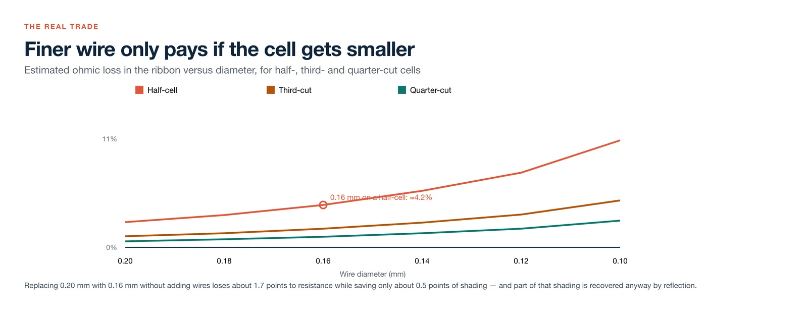
Take a 210R format with 24 wires per cell. On a half-cell, 0.20 mm ribbon gives about 2.5% ohmic loss; at 0.16 mm that rises to about 4.2% — 1.7 points lost. Shading falls from 2.6% to 2.1%, only 0.5 points, and some of that is recovered by reflection off the round wire. Finer wire without more wires loses power.
The other two lines in the chart show the way out: cut the cell smaller. A third-cut cell carries two-thirds of the current over two-thirds of the path, so ribbon loss falls to 44% of the half-cell value; a quarter-cut falls to 25%. At 0.16 mm with third-cut cells, loss is back to about 1.9%; 0.12 mm needs quarter-cut cells to return to around 2%.
The second bill: force, alignment and joints
0BB ribbon uses annealed soft copper with a yield strength near 100 MPa. Yield force is about 3.1 N at 0.20 mm, 2.0 N at 0.16 mm and only 0.8 N at 0.10 mm — roughly the weight of an 80 g object. A stringer pulls dozens of wires at speed; any tension fluctuation stretches the fine wire thinner and raises resistance further.
Bending stiffness scales with the fourth power of diameter: 0.16 mm has 41% of the stiffness of 0.20 mm, and 0.10 mm only 6% — it behaves like thread and will not stay straight. Ribbon makers already report alignment issues at 0.20 mm in 0BB, mitigated by higher yield strength and about 2% pre-tension, which in turn makes the wire harder and increases stress on the cell.
Finally, the joint. 0BB ribbon lands on fingers only twenty or thirty microns wide, so each intersection has little contact area. Finer wire means less solder, a contact closer to a point, and worse contact resistance and pull-off force. Coating concentricity is harder too: 3 µm of eccentricity is tolerable at 0.20 mm and may leave one side starved at 0.10 mm.
Where the limit sits
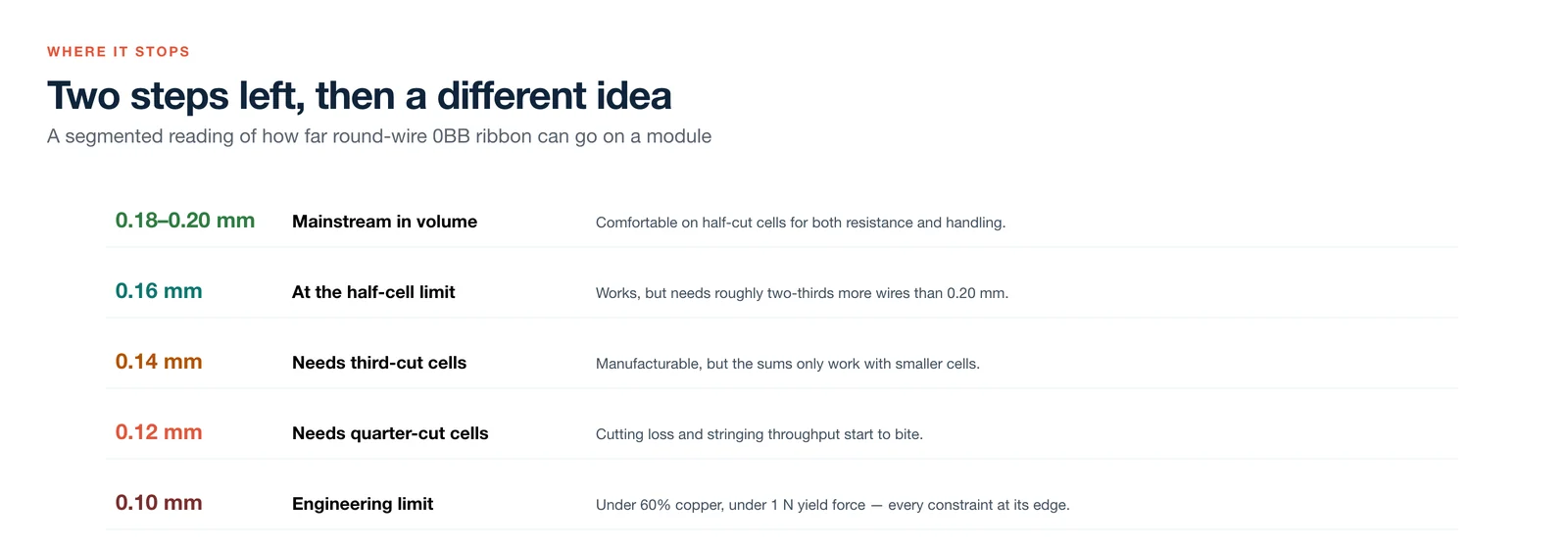
0.18–0.20 mm is the confirmed volume mainstream. 0.16 mm is already close to the sensible half-cell limit and needs about two-thirds more wires. 0.14 mm is manufacturable but hard to justify on half-cells, better paired with third-cut. 0.12 mm needs quarter-cut cells. 0.10 mm is the visible engineering limit: under 60% copper, under 1 N yield force, every constraint at its edge. Below that, round wire stops paying and the answer is a different concept — shaped ribbon, conductive adhesive interconnection, or a change on the cell metallisation side.
The conclusion is a system answer, not a ribbon answer: how fine the wire goes depends less on whether the ribbon maker can draw it than on whether module makers will cut smaller cells and run denser wire arrays. How fast that happens depends on the silver price, on how thin wafers get, and on how quickly multi-cut equipment gets cheaper.
How ZOEAST PV applies this
ZOEAST PV specifies ribbon by diameter, yield strength, coating thickness and straightness rather than by price per kilogram, because those four properties decide whether a stringer runs and whether a joint survives. For current TOPCon modules we stay with the proven 0.18–0.20 mm range and half-cut cells; finer wire only enters a specification together with a smaller cell format and a validated lamination recipe.
If a project calls for 0BB interconnection, we would quote it with the joint-level test data — pull strength, thermal cycling and damp heat — rather than the headline silver saving. Talk to the engineering team about module specifications, or see the current module range.
Calculation notes: simplified model with a 210R format, 15.5 A full-cell current, 0.606 V per cell, linear current accumulation along the cell, front-plus-rear loss taken as (2/3)·I²R/n; copper resistivity 0.0172 and solder 0.145 Ω·mm²/m; coating 12 µm per side; contact resistance, finger loss and optical reflection gain excluded. Results show trends, not measured values for a specific product. Production-diameter data follow Tongxiang's 2024 interim report, Zhongyuan Securities, TaiyangNews, Dongwu and Tianfeng research, and a Jolywood patent. Figures: ZOEAST PV, redrawn in English.